- 您现在的位置:买卖IC网 > Sheet目录528 > TRF7970AEVM (Texas Instruments)EVAL MODULE FOR TRF7970A
�� �
�
�TRF7970A�
�www.ti.com�
�SLOS743K� –� AUGUST� 2011� –� REVISED� APRIL� 2014�
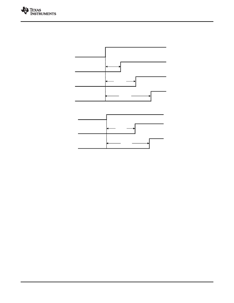
�When� user� MCU� is� controlling� EN� and� EN2,� a� delay� of� 1� ms� between� EN� and� EN2� must� be� used.� If� the�
�MCU� controls� only� EN,� EN2� is� recommended� to� be� connected� to� either� V� IN� or� GND,� depending� on� the�
�application� MCU� requirements� for� V� DD_X� and� SYS_CLK.�
�VIN�
�2� ms�
�SS�
�EN2�
�EN�
�5� ms�
�6� ms�
�Figure� 6-3.� Nominal� Start-Up� Sequence� Using� SPI� With� SS� (MCU� Controls� EN2)�
�VIN�
�5� ms�
�EN2�
�6� ms�
�EN�
�Figure� 6-4.� Nominal� Start-Up� Sequence� Using� Parallel� (MCU� Controls� EN2)�
�This� start-up� mode� lasts� until� all� of� the� regulators� have� settled� and� the� 13.56-MHz� oscillator� has� stabilized.�
�If� the� EN� input� is� set� high� (EN� =� 1)� by� the� MCU� (or� other� system� device),� the� reader� stays� active.� If� the� EN�
�input� is� not� set� high� (EN� =� 0)� within� 100� μs� after� the� SYS_CLK� output� is� switched� from� auxiliary� clock� (60�
�kHz)� to� high-frequency� clock� (derived� from� the� crystal� oscillator),� the� reader� system� returns� to� complete�
�Power-Down� Mode� 1.� This� option� can� be� used� to� wake-up� the� reader� system� from� complete� Power� Down�
�(PD� Mode� 1)� by� using� a� pushbutton� switch� or� by� sending� a� single� pulse.�
�After� the� reader� EN� line� is� high,� the� other� power� modes� are� selected� by� control� bits� within� the� chip� status�
�control� register� (0x00).� The� power� mode� options� and� states� are� listed� in� Table� 6-3� .�
�When� EN� is� set� high� (or� on� rising� edge� of� EN2� and� then� confirmed� by� EN� =� 1)� the� supply� regulators� are�
�activated� and� the� 13.56-MHz� oscillator� started.� When� the� supplies� are� settled� and� the� oscillator� frequency�
�is� stable,� the� SYS_CLK� output� is� switched� from� the� auxiliary� frequency� of� 60� kHz� to� the� 13.56-MHz�
�frequency� derived� from� the� crystal� oscillator.� At� this� point,� the� reader� is� ready� to� communicate� and� perform�
�the� required� tasks.� The� MCU� can� then� program� the� chip� status� control� register� 0x00� and� select� the�
�operation� mode� by� programming� the� additional� registers.�
�?�
�?�
�?�
�?�
�Stand-by� Mode� (bit� 7� =� 1� of� register� 0x00),� the� reader� is� capable� of� recovering� to� full� operation� in�
�100� μs.�
�Mode� 1� (active� mode� with� RF� output� disabled,� bit� 5� =� 0� and� bit� 1� =� 0� of� register� 0x00)� is� a� low� power�
�mode� which� allows� the� reader� to� recover� to� full� operation� within� 25� μs.�
�Mode� 2� (active� mode� with� only� the� RF� receiver� active,� bit� 1� =� 1� of� register� 0x00)� can� be� used� to�
�measure� the� external� RF� field� (as� described� in� RSSI� measurements� paragraph)� if� reader-to-reader�
�anticollision� is� implemented.�
�Modes� 3� and� 4� (active� modes� with� the� entire� RF� section� active,� bit� 5� =� 1� of� register� 0x00)� are� the�
�normal� modes� used� for� normal� transmit� and� receive� operations.�
�Copyright� ?� 2011–2014,� Texas� Instruments� Incorporated�
�Submit� Documentation� Feedback�
�Product� Folder� Links:� TRF7970A�
�Detailed� Description�
�19�
�发布紧急采购,3分钟左右您将得到回复。
相关PDF资料
TRM-418-LT
TRANSCEIVER RF 418MHZ LT SERIES
TRM-900-NT
RF TXRX 915MHZ NT SERIES
TRX08GVP2540
TXRX OPT SCFF 8.5GB/S 850NM
TS-320240BRNO
TCH PANEL 140X104 RESISTIVE MONO
TS-TFT3.5Z
TOUCH PANEL 140X1.4.0 TFT
TS3-75B3
SENSOR THERMAL MOXIE NTC 75C
TSL26711FN
IC PROXIMITY DETECTOR 6-DFN
TSOP57238TT1
IC IR RCVR MODULE 38KHZ
相关代理商/技术参数
TRF7970ARHBR
功能描述:IC RFID/NFC AFE 13.56MHZ 32QFN RoHS:是 类别:RF/IF 和 RFID >> RFID IC 系列:- 其它有关文件:CR14 View All Specifications 标准包装:1 系列:- RF 型:收发器 频率:13.56MHz 特点:ISO14443-B 封装/外壳:16-SOIC(0.154",3.90mm 宽) 供应商设备封装:16-SO 包装:Digi-Reel® 其它名称:497-5719-6
TRF7970ARHBT
功能描述:IC RFID/NFC AFE 13.56MHZ 32QFN RoHS:是 类别:RF/IF 和 RFID >> RFID IC 系列:- 其它有关文件:CR14 View All Specifications 标准包装:1 系列:- RF 型:收发器 频率:13.56MHz 特点:ISO14443-B 封装/外壳:16-SOIC(0.154",3.90mm 宽) 供应商设备封装:16-SO 包装:Digi-Reel® 其它名称:497-5719-6
TRF7970ATB
功能描述:RFID应答器 TRF7970A Target Brd RoHS:否 制造商:Murata 存储容量:512 bit 工作温度范围:- 40 C to + 85 C 安装风格:SMD/SMT 封装 / 箱体: 封装:Reel
TRF79A6AA17LB000
制造商:Opnext 功能描述:XFP FORM FACTOR - Boxed Product (Development Kits)
TRF79A6AA18LB000
制造商:Opnext 功能描述:XFP FORM FACTOR - Boxed Product (Development Kits)
TRF79A6AA19LB000
制造商:Opnext 功能描述:XFP FORM FACTOR - Boxed Product (Development Kits)
TRF79A6AA20LB000
制造商:Opnext 功能描述:XFP FORM FACTOR - Boxed Product (Development Kits)
TRF79A6AA21LB000
制造商:Opnext 功能描述:XFP FORM FACTOR - Boxed Product (Development Kits)